
| NEWS | |||||||
| ABOUT | |||||||
| PRODUCTS AND SERVICES | |||||||
|
| |||||||
| PLACE AN ORDER | |||||||
| DOWNLOAD | |||||||
| HELPFUL HINTS | |||||||
| FAQ | |||||||
| LINKS | |||||||
| SEARCH | |||||||
| SITE MAP | |||||||
| CONTACT | |||||||
| русский |
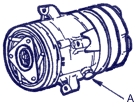
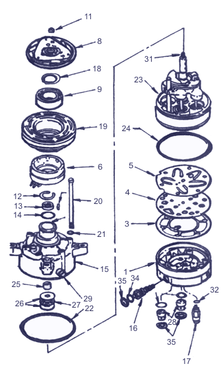
Compressor repairHaving read this chapter, you will learn how on the basis of carried out below order about disassembly and assembly of the compressor to make his fine and major overhaul. The information concerning a principle of work of the compressor and its general device is contained in 1-st and 2-nd parts of this book.
At repair of the compressor it is necessary to watch that the dirt has not got on external surfaces and in internal cavities. For qualitative repair it is necessary to observe cleanliness on a workplace and to use clean tools. Before serving the compressor on the automobile or to dismantling it for repair in stationary conditions, it is necessary carefully to clean the compressor and pipeline nipple connections outside. After disassembly of a detail of the compressor it should be preserved in purity. Before assembly of a detail it is necessary to be washed out in trichlorethane, ligroin, standard solvent, kerosene or similar solvents and to dry up with compressed dry air. For rubbing details it is possible to use only the fabrics which are not leaving fibres and pile.
The description of operations given below on repair of the compressor is designed for work with the unit removed from the automobile in conditions of workshop, except for the separate specified cases. The sequence of technological operations takes into account an opportunity of convenient access to separate details of the compressor. After dismantle of the compressor from the automobile it is necessary to completely merge the oil which has stayed in it to measure and write down volume of merged oil. In the subsequent this amount of oil is replace with fresh one: marks 525 if the system of conditioning is charged with refrigerant R-12, marks PAG if the system works on refrigerant R-134а.
|
 The automobiles equipped with the compressor may differ an arrangement of arms of fastening, the device of a drive, pulleys, connections and in refueling capacity of the system of air-conditioning. Nevertheless, the basic operations on repair of compressors remain common.