
| NEWS | |||||||
| ABOUT | |||||||
| PRODUCTS AND SERVICES | |||||||
|
| |||||||
| PLACE AN ORDER | |||||||
| DOWNLOAD | |||||||
| HELPFUL HINTS | |||||||
| FAQ | |||||||
| LINKS | |||||||
| SEARCH | |||||||
| SITE MAP | |||||||
| CONTACT | |||||||
| русский |
Basic scheme and components of ATC system
|
|
Checking:
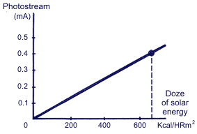
They measure the current through having connected to the solar gauge wires. (At a doze of a solar energy of 600 Kcal / HRЈm2 value of the current Ч 0,4 mA).
 Electric motor of air mixing flap
Location:
The right side of the heater (ј) back case.
Function:
The electric motor is connected to the air mixing flap with the lever, and at starting of the electric motor of the flap opening, and to the controller the transformed pressure of the feedback whose value varies from a degree of opening of air mixing flap is delivered.
Checking:
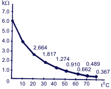
After the detachment of the socket of electric motor of air mixing flap, after having connected the measuring instrument of resistance to plugs "ј5" and "A11" PBR, , they measure the value of resistance. At opening of the electric motor of air mixing flaps on 40°C, the value of resistance PBR is 5,48 kOm.
|
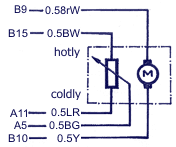 |
Diagram of dependence of electric motor resistance on temperature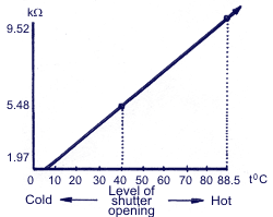 |
 Vacuum solenoid-operated valve
Location:
Base plate in a box for gloves.
Function:
5 In electromagnetic valves on signals of the switch of exhaust outlets modes and the switch of choice of suction aperture (REC, FRE) they actuate with vacuum all operating mechanisms of modes.
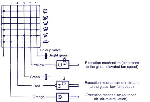
Mode control / executing mechanisms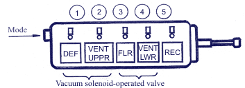 1 Ц air stream to the glass |
Modes of air stream - to the glass (heater maximum efficiency)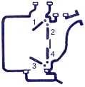 |
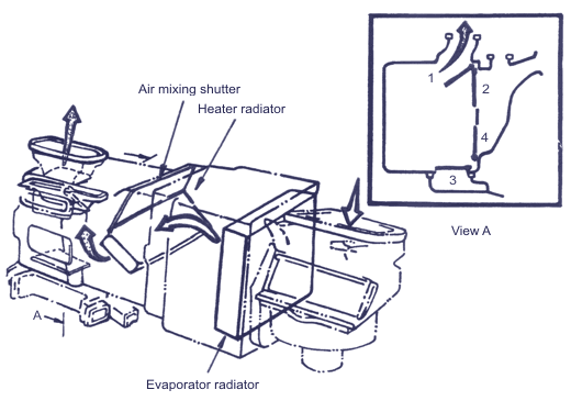 |
Upwards to the front (position of maximum cooling) switch FRE/REC is switched - off)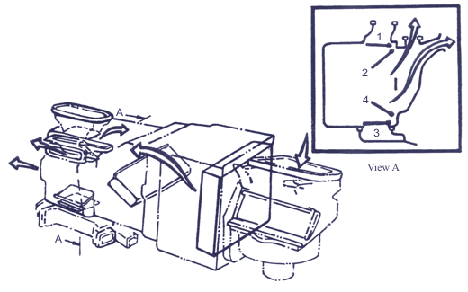 |
Upwards to the front (position of maximum cooling) switch FRE/REC is switched - on)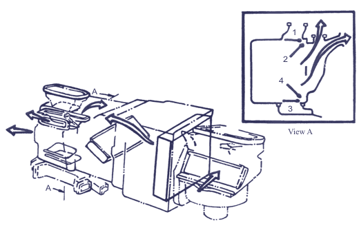 |
To the floor ((position of maximum cooling) switch FRE/REC is switched - off)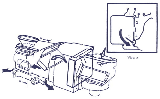 |
Separation of streams (mixing of hot and cold streams) switch FRE/REC is switched - off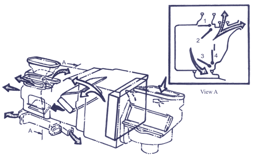 |
 Air blower relay
Location:
Relay box of under-bonnet space.
Function:
Switches the speed of the air blower electric motor to 1 stage (LO), 2 stage (ML), 3 stage (ћЌ), 4 stage (HI) depending on the air stream determined by the circuit of a drive of the controller air blower.
|
Chain of air blower control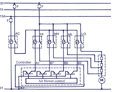 |
 Switches of different purpose
Location:
The front side of the controller panel.
Function:
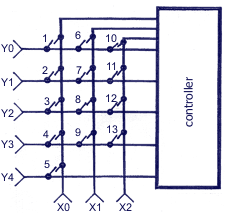
With the help of the switch it transfers the condition of the switch set by controller MICOM which is made by the method of matrix key.
|
|
 Controller
Location:
The right side of the driverТs seat.
Function:
Automatically adjusts temperature of interior and an air stream with the help of air mixing flap and the air blower relay by reception and reading of the entrance signals coming from different gauges, switch of the condition of temperature adjustment, PBR. Actuating of target and suction apertures, interruption of the compressor is carried out manually from the signals set up by the switch (switch and controller are made as one whole).
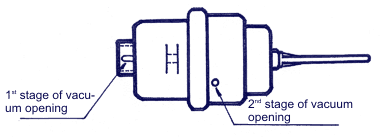
 2 step vacuum diaphragm
Location:
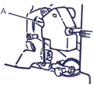
Are set up on the site of heater (A) channel the mode flap.
Function:
Using underpressure of the engine, it starts each flap of the heater mode depending on work of the vacuum electromagnetic valve.
1 stage: moving on 25 mm.
2 stage: moving on 15 mm.
In total 40 mm - moving.
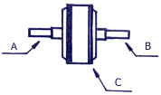
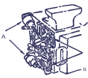 B - Levers of mode flap control |
 |
 Vacuum damping valve
|
Location:
Hose between the vacuum electromagnetic valve and 2-stage vacuum diaphragm.
Functions:
At influence of underpressure of the engine on 2-stage vacuum diaphragm, there detains underpressure on 4±2 seconds on diaphragm of 2-stage action for prevention of internal diaphragm damage.
Attention: on the case of vacuum damping valve, on black and white color there is a strip. White color should be directed to the side of the vacuum electromagnetic valve.
 Heater vacuum valve
|
Location:
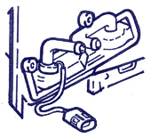
Near to the electric motor of air mixing flap.
Function:
When the air mixing flap is in a position of maximal cooling, the heater valve is influenced by underpressure of the engine and blocks access of the cooling liquid of the engine into the heater core.
 Suction hose
Location:
Set up together with internal air thermode.
Function:
Makes suction of the saloon air, using the difference of pressure arising at ventilation and connection of the hose end with air blower so that it would be possible to suck up to the built - in internal air thermode for reaction of temperature of the automobile saloon air.

