General description of ACC system
The automatic air-conditioner is adjusted by sending the signals on executing mechanisms on the basis of calculation of necessary temperature of sucking air at receipt on a computer of the information on the desirable chosen temperature and from each gauge (thermodes of internal and external air, solar gauge, gauge of water temperature, thermode behind evaporator, gauge of the automobile speed), and also processings of entrance signals of various sorts of switches, potentiometers and other gauges.
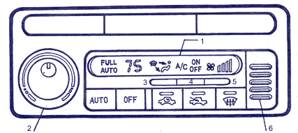
| The control panel of the automatic conditioner |
 |
1 Ц designation of operation and diagnostics of malfunctions
2 Ц temperature regulator handle
3 Ц button MODE |
4 Ц button ЂOFFї (switch-off) of the compressor
5 Ц button ЂONї (switch-on) of the fan
6 Ц suction aperture |
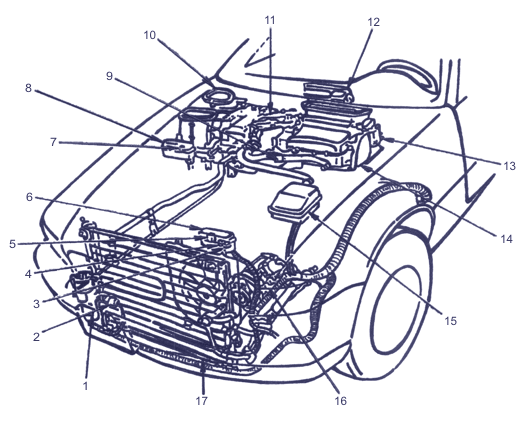
| Arrangement of the ACC system elements on the automobile |
 |
1 Ц a receiver a drier
2 Ц pressure 3 switch socket
3 Ц radiator fan relay
4 Ц condenser fan relay
5 Ц main relay of radiator fan
6 Ц a box of relay "A" of under-bonnet area
7 Ц compressor muff relay
8 Ц box of relay "C" of under-bonnet area
9 Ц heater valve |
10 Ц air blower block
11 Ц cable of the valve of a heater
12 Ц panel of the heater control
13 Ц electric motor of MODE control
14 Ц evaporator
15 Ц box of relay and safety locks of under-bonnet area
16 Ц compressor
17 Ц condenser |
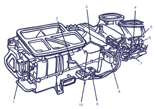
| Elements of the block of heater / evaporator |
 |
1 Ц electric motor of control MODE
2 Ц thermode
3 Ц thermode after evaporator
4 Ц two-contact socket of the air blower electric motor
5 Ц relay of high speed of the air blower electric motor
6 Ц relay of the air blower electric motor
7 Ц power transistor
8 Ц electric motor of internal / external air control
9 Ц electric motor of maximum cooling
10 Ц electric motor of air mixing control |
|


